Potentiometers
This section will help you to reason how to connect potentiometers, if you use them as voltage dividers.
Step one: pinout
Determine the pinout of your potentiometer.
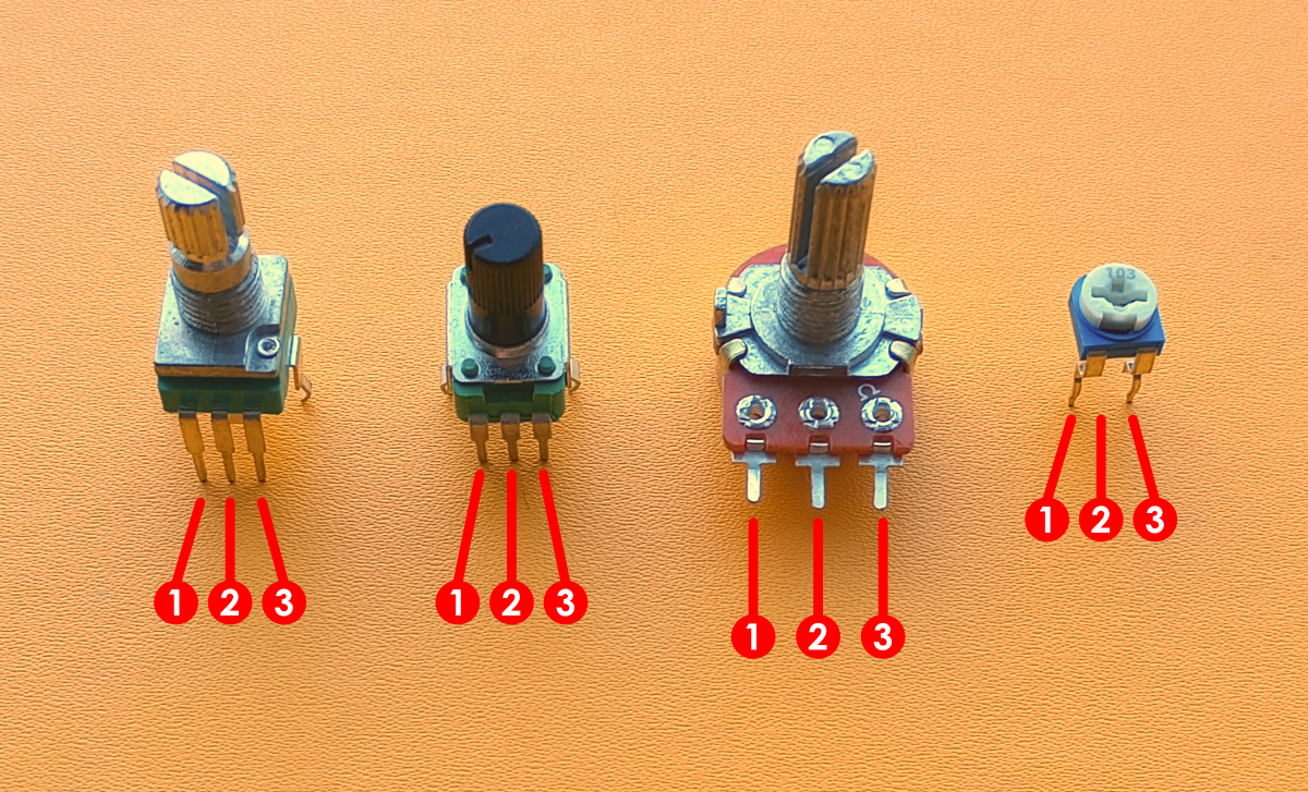
If you hold your potentiometer like in the image above you can simply count the pin numbers from left to right (or look at the associated data sheets). Remember this orientation and you will always find the correct pinout!
Step two: signal out
Which pin should be the attenuated output?
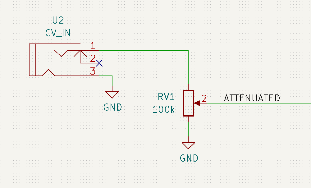
This one is simple. If you use your potentiometer as a voltage divider (see image above), the attanuated output signal should come from the center pin (2).
Step three: positions
Reason about how your potentiometer should function.
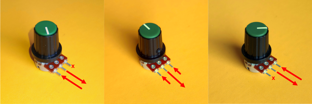
Look at the image above and notice three important positions:
- Fully counterclockwise position (first one). In this position center pin 2 will 'feel' the same as what pin 1 'feels'. They are basically directly connect now, so if pin 1 is ground, pin 2 is ground too, etc. The signal from pin 3 has no influence here.
- Centered position (middle one). In this position the center pin 2 will 'feel' 50% of what pin 1 'feels' and 50% of what pin 3 'feels'.
- Fully clockwise position (third one). In this position pin 2 will 'feel' the same as what pin 3 'feels'. So, if pin 1 is the incomming signal, pin 2 is the incomming signal too, etc. The signal from pin 1 has no influence here.
Rule of thumb for: Pin 1
What should the output value be when the potentiometer is rotated fully counterclockwise?
Give this value to pin 1.
Rule of thumb for: Pin 3
What should the output value be when the potentiometer is rotated fully clockwise?
Give this value to pin 3.
Step four: conclusion
Normally you want the output signal fully closed when you turn it fully counterclockwise. Therefore, I hope you can reason now that....
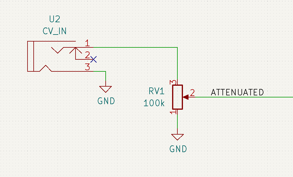
For a standard voltage divider setup:
- Pin 1 connects to ground.
- Pin 2 connects to output.
- Pin 3 connects to input signal.